11. How To
11.1. How to install VMWare ESXi on Physical Server
- Requirement of physical server
The physical server must support ESXi 6.0 and it should be allocated at least 3 NIC ports. The first NIC port is used for the admin network connection. The second and third NIC ports are used for control network connection(The second NIC is required. The third NIC is optional). The fourth NIC port is used for data network connection (optional).
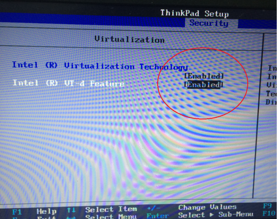
Virtual InfraSIM servers runs in the best performance if hardware-assisting technology has been enabled on underlying physical machines. These technology includes VT-d feature and AMD-V for processors from Intel and AMD.
Note
Physical machine - enable VT-d in BIOS
- Setting Up Network Connections
You must have IP addresses for the physical servers in the test environment to be used to configure the VMKernal port of ESXi and called as ESXi_Admin_IP.
- Allocate or reserve a static IP address from the Lab admin.
- Connect the server’s admin NIC ports into the Lab network.
- To set up a multiple server environment, connect Port C1 on each server by using an Ethernet switch.
- Install ESXi 6.0
From the VMWare web site, a 60-day free trial version is available after user registration.
- Go to https://my.vmware.com/web/vmware/details?downloadGroup=ESXI600&productId=490&rPId=7539
- Download the VMWare vSphere Hypervisor 6.0 (ESXi6.0) ISO image.
- Install ESXi 6.0 on each physical server.
- Configure the static IP address ESXi_Admin_IP on first NIC port.
- Set the Administrator user name by using the format <User Name>.
- Set the Administrator Password by using the format <Password>.
- Installing VMWare vSphere Client (Remote System)
- Go to the VMWare web site.
- Download the VMWare vSphere Client.
- Install the client on a remote system that can connect to the physical servers.
- Configuring the Virtual Network
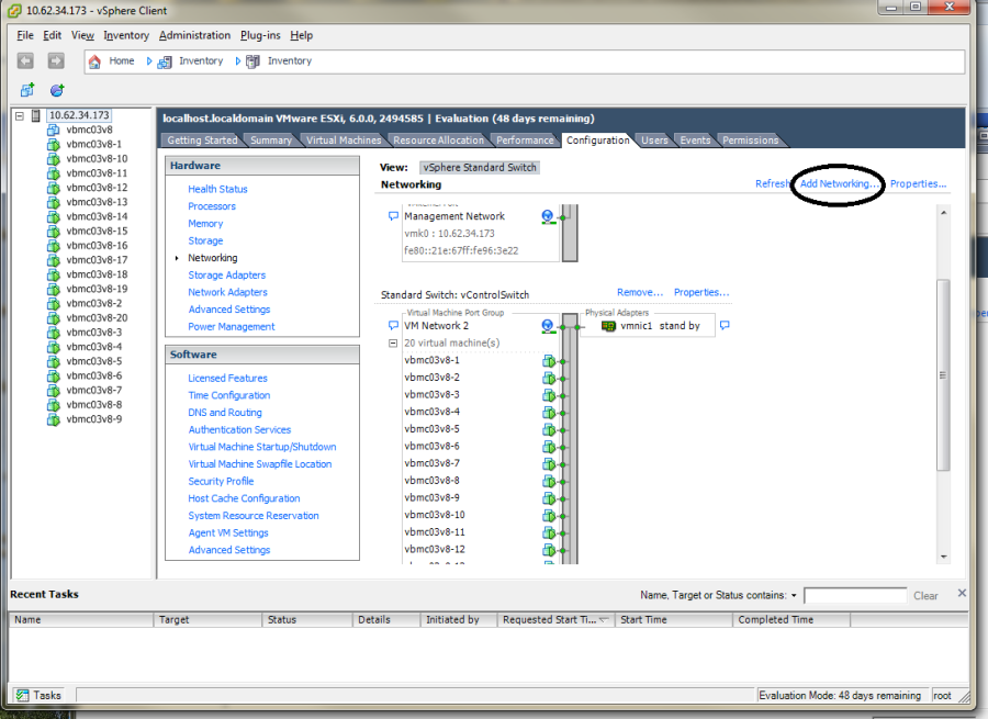
Launch the vSphere client and connect to ESXi on the physical server by using ESXi_Admin_IP.
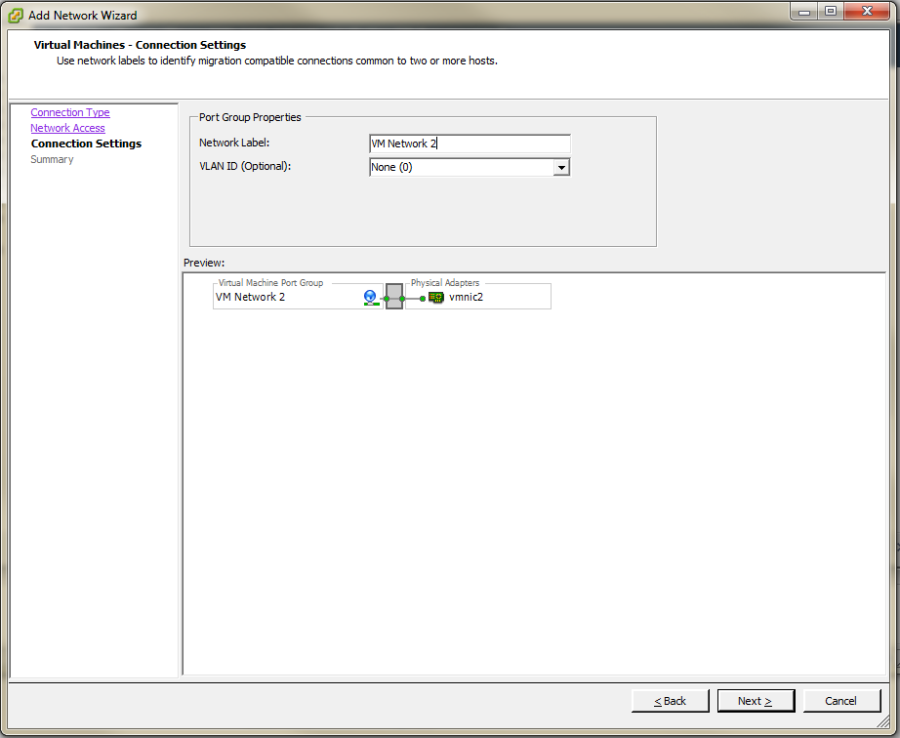
On the Configuration tab, click Add Networking, to create the Control vSwitch. In the example, the network label is “VM Network 2”.
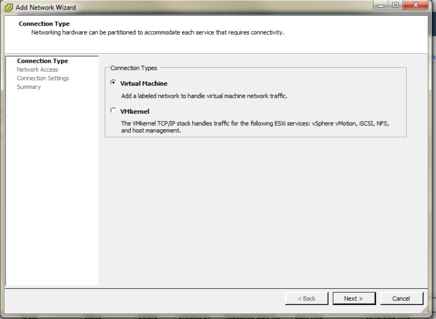
Select Virtual Machine
Select Create a vSphere standard switch > vmnic2.
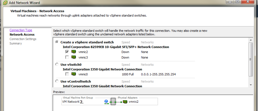
In the Network Label field, type port group name on target switch.
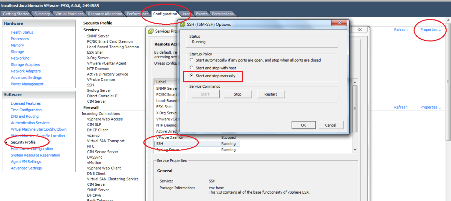
Enable the SSH service on ESXi. To do this, open the Configuration tab and select Security Profile. Then select SSH and click Properties to set the SSH (TSM-SSH) to start and stop manually.
Note
Login to the ESXi server through SSH and echo by issuing the “vhv.enable = “TRUE”“ command to the /etc/vmware/config file. This command enables nested ESXi and other hypervisors in vSphere 5.1 or higher version. This step only needs to be done once by using the command: echo ‘vhv.enable = “TRUE”’ >> /etc/vmware/config.
Note
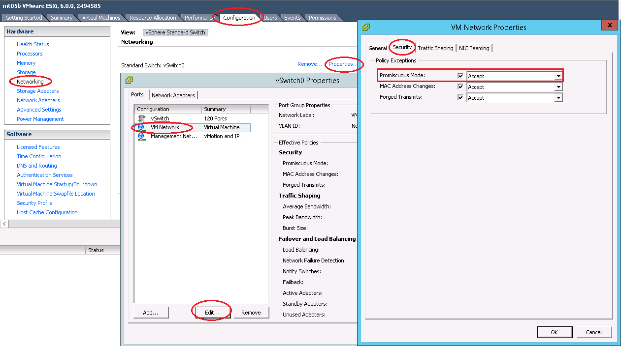
Set Promiscuous Mode to Accept and tick Override. To do this, open the Configuration tab and select Networking. Then click Properties of the vSwitch, choose port group, edit, security, tick the checkbox to override setting and select Accept.
11.2. How to deploy InfraSIM virtual server on different type of platforms
- There are desires to deploy virtual server on different types of hypervisor like:
- VirtualBox
- KVM
- VMWare product, both VMWare vSphere or VMWare workstation
2 possible ways to achieve this:
- Create virtual machine image for corresponding hypervisor beforehand and them import that image onto hypervisors - InfraSIM application is ready in operating system running in virtual machines or containers on top of specified hypervisor or platform. These images are: OVA file for VMWare workstation or vSphere; QCOW2 file for KVM/QEMU; BOX or vagrant/VirtualBox, etc. Below listed some steps on how to deploy these template into different systems:
- Spin-up virtual machines running Ubuntu 64-bit 16.04 OS on desired hypervisor and then install infrasim-compute application. You may also leverage Chef or Ansible to deploy multiple virtual server instances into multiple virtual machines.
11.3. How to simulate another server - Under construction
InfraSIM also provided many utilities, interfaces for developers to build one simulation solution for a physical node that has not been supported by infraSIM. This sections walk through steps required to build one simulation for one specific server node.
To simulate a real hardware server, you have to get the server fru’ data:
$ cd data
Under this directory, you can find “vnode.emu” file. In this file, we keep server fru’ data here, like:
$ mc_add_fru_data 0x20 0x0 0x100 data \
  0x01 0x00 0x01 0x04 0x0f 0x00 0x00 0xeb \
  0x01 0x03 0x17 0x00 0xcd 0x51 0x54 0x46 \
  0x43 0x4a 0x30 0x35 0x31 0x36 0x30 0x31 \
  ......
You can use ipmitool to get BMC sensor’s data:
$ ipmitool -U <your-account> -P <your-password> -I lanplus -H <your-BMC-IP> fru read <fru ID> fru.bin
call fru_gen.py script to dump fru.bin to hex format:
$ cp ../../tools/data_generater/fru_gen.py ./
$ python fru_gen.py fru.bin
fru_result will be generated, replace original fru data with the expected one in this file.
Same as fru, in “vnode.emu” file, we keep server sensors’ data here, like:
$ sensor_add 0x20 0x0 0x01 0x02 0x01
  main_sdr_add 0x20 \
  0x00 0x00 0x51 0x02 0x2a \
  0x20 0x00 0x01 0x15 0x01 0x67 0x40 0x09 0x6f 0x71 0x00 0x71 0x00 0x71 0x00 0xc0 \
  0x00 0x00 0x01 0x00 0x00 0x00 0x00 0x00 0x00 0x00 0xcf 0x50 0x77 0x72 0x20 0x55 \
  0x6e 0x69 0x74 0x20 0x53 0x74 0x61 0x74 0x75 0x73
$ sensor_set_value 0x20 0x0 0x01 0x0 0x1

You can use ipmitool to get BMC sensor's data::

$ ipmitool -U <your-account> -P <your-password> -I lanplus -H <your-BMC-IP> sdr dump sensors
The above command will dump your server BMC sensors’ data to the file named: “sensors” Generally, the sensor file contains binary data, we have to convert it to strings:
$ cp ../../tools/data_generater/sensors_gen.sh ./
$ ./sensor_gen.sh
After the command, you will get the file named: “all_sdr_sensors”:
Use "all_sdr_sensors" file content to replace "vnode.emu" file of all "sensor_add" sections
    **Notice: This step is not necessary for your node unless you want to emulate the real BMC sensors' data.**
SMBIOS data is also needed, which can be got by using the command:
$ dmidecode --dump-bin <your-vnode-name>_smbios.bin
Build your vnode with real hardware fru, sensors and smbios data.:
$ make <your-vnode-name>
Enjoy your customized node.
11.4. How to simulate another vPDU - Under construction
InfraSIM provided ServerTech and Panduit PDU simulation initially. InfraSIM also provided many utilities, interfaces for developers to build simulation solution for other physical PDUs. This sections walk through all steps required to build one simulation for other PDU infraSIM doesn’t support yet.
How to retrieve data from physical PDU
If you want to retrieve PDU MIB data, you should have snmpsim installed on your environment.Then run the following command to produce MIB snapshot for the PDU:
# snmprec.py --agent-udpv4-endpoint=<PDU IP address>; --start-oid=1.3.6 --output-file=/path/<target snmprec file>; --variation-module=sql --variation-module-options=dbtype:sqlite3,database:/path/<target pdu database file>,dbtable:snmprecFor more details of how to use snmprec.py, please go to section Producing SNMP snapshots at snmpsim home page for more help.
How to simulate physical PDU in InfraSIM
Once you retrieved data from physical PDU, the next step is to add a virtual PDU in InfraSIM for this physical server. The following steps will guide you how to do:
- Create a directory named PDU name at idic/vpdu
- Create a directory data at idic/vpdu/<PDU name>/data, and copy the data you get from physical server into data directory.
- Copy .config and Makefile into idic/vpdu/<PDU name>, and update target name in Makefile and .config
- Clone vpduserv, and implement the new pdu logic based on vendor’s PDU spec.
11.5. How to integrate RackHD with InfraSIM
RackHD is an open source project that provides hardware orchestration and management through APIs. For more information about RackHD, go to http://rackhd.readthedocs.io.
The virtual hardware elements(virtual compute node, virtual PDU, virtual Switch) simulated by InfraSIM can be managed by RackHD.
The following picture shows the deployment model for the integration of InfraSIM and RackHD:
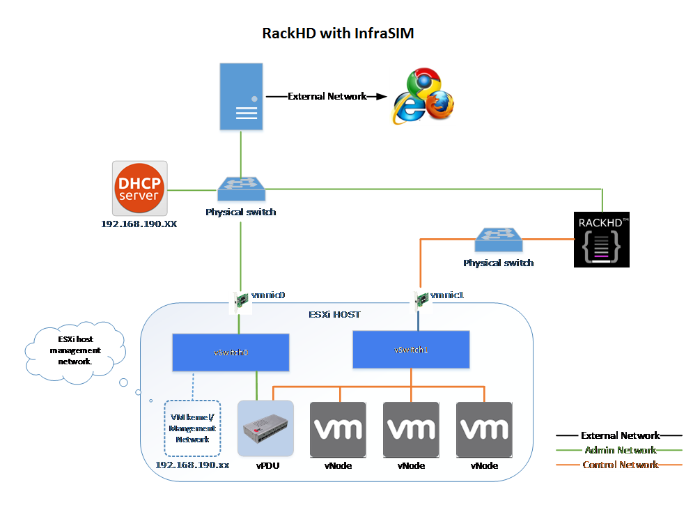
Please follow up below steps to step the entire environment. After that, RackHD can discover and manage the virtual server and virtual PDU just as the real physical server and PDU.
- Please refer RackHD document(http://rackhd.readthedocs.org/en/latest/getting_started.html) to setup the RackHD Server. RackHD server should be configured with as least two networks, “Admin network” and “Control Network”.
- “Admin Network” is used to communicate with external servers
- “Control Network” is used to control the virtual servers.
Deploy virtual compute node and virtual PDU on ESXi with the network connection as in the pictures show. The ESXi show have network connection with the RackHD server.
After you setup the environment successfully, you can get the server information and control the servers by RackHD APIs. More information about how RackHD APIs communicate with the compute server and PDU, Please refer http://rackhd.readthedocs.org/en/latest/rackhd/index.html#rackhd-api