11. How To
11.1. How to install VMWare ESXi on Physical Server
- Requirement of physical server
The physical server must support ESXi 6.0 and it should be allocated at least 3 NIC ports. The first NIC port is used for the admin network connection. The second and third NIC ports are used for control network connection(The second NIC is required. The third NIC is optional). The fourth NIC port is used for data network connection (optional).
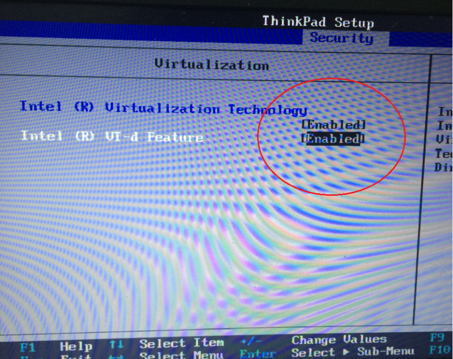
Virtual InfraSIM servers runs in the best performance if hardware-assisting technology has been enabled on underlying physical machines. These technology includes VT-d feature and AMD-V for processors from Intel and AMD.
Note
Physical machine - enable VT-d in BIOS
- Setting Up Network Connections
You must have IP addresses for the physical servers in the test environment to be used to configure the VMKernal port of ESXi and called as ESXi_Admin_IP.
- Allocate or reserve a static IP address from the Lab admin.
- Connect the server’s admin NIC ports into the Lab network.
- To set up a multiple server environment, connect Port C1 on each server by using an Ethernet switch.
- Install ESXi 6.0
From the VMWare web site, a 60-day free trial version is available after user registration.
- Go to https://my.vmware.com/web/vmware/details?downloadGroup=ESXI600&productId=490&rPId=7539
- Download the VMWare vSphere Hypervisor 6.0 (ESXi6.0) ISO image.
- Install ESXi 6.0 on each physical server.
- Configure the static IP address ESXi_Admin_IP on first NIC port.
- Set the Administrator user name by using the format <User Name>.
- Set the Administrator Password by using the format <Password>.
- Installing VMWare vSphere Client (Remote System)
- Go to the VMWare web site.
- Download the VMWare vSphere Client.
- Install the client on a remote system that can connect to the physical servers.
- Configuring the Virtual Network
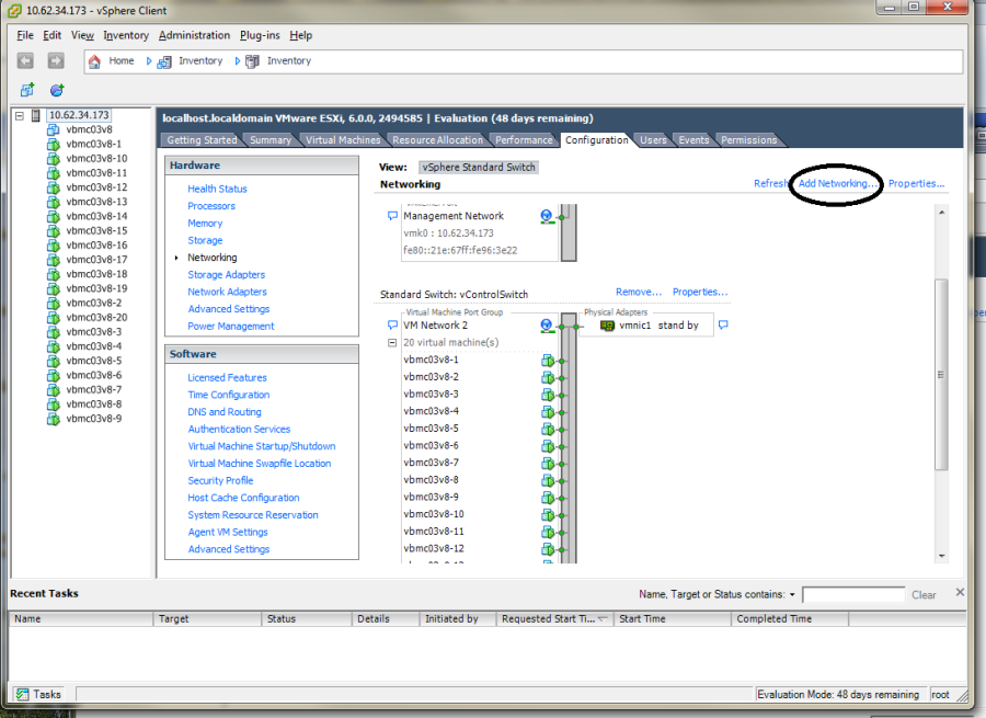
Launch the vSphere client and connect to ESXi on the physical server by using ESXi_Admin_IP.
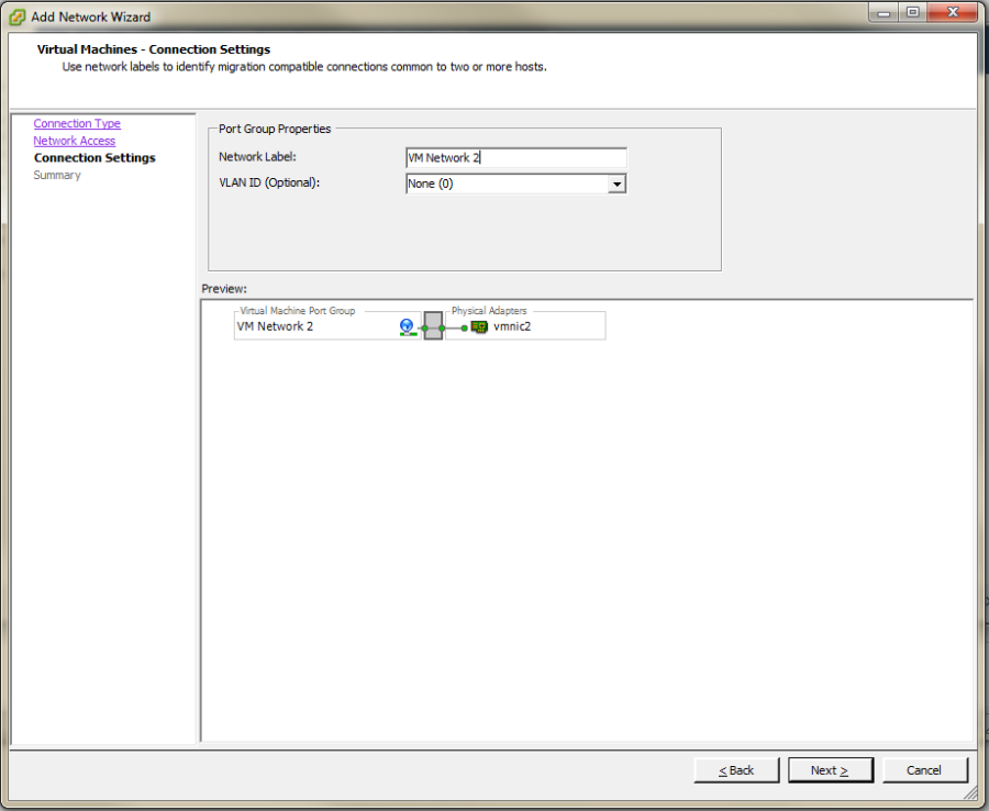
On the Configuration tab, click Add Networking, to create the Control vSwitch. In the example, the network label is “VM Network 2”.
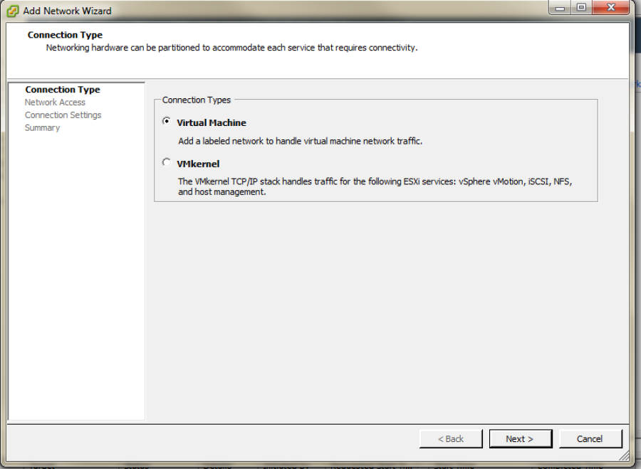
Select Virtual Machine
Select Create a vSphere standard switch > vmnic2.
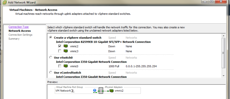
In the Network Label field, type port group name on target switch.
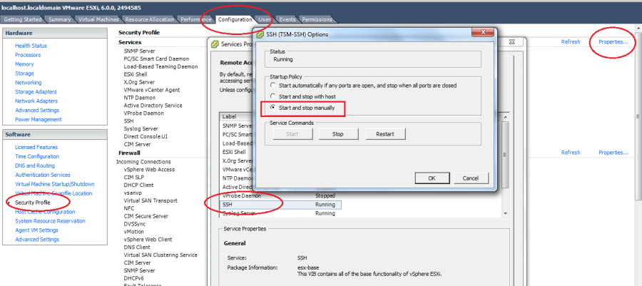
Enable the SSH service on ESXi. To do this, open the Configuration tab and select Security Profile. Then select SSH and click Properties to set the SSH (TSM-SSH) to start and stop manually.
Note
Login to the ESXi server through SSH and echo by issuing the “vhv.enable = “TRUE”“ command to the /etc/vmware/config file. This command enables nested ESXi and other hypervisors in vSphere 5.1 or higher version. This step only needs to be done once by using the command: echo ‘vhv.enable = “TRUE”’ >> /etc/vmware/config.
Note
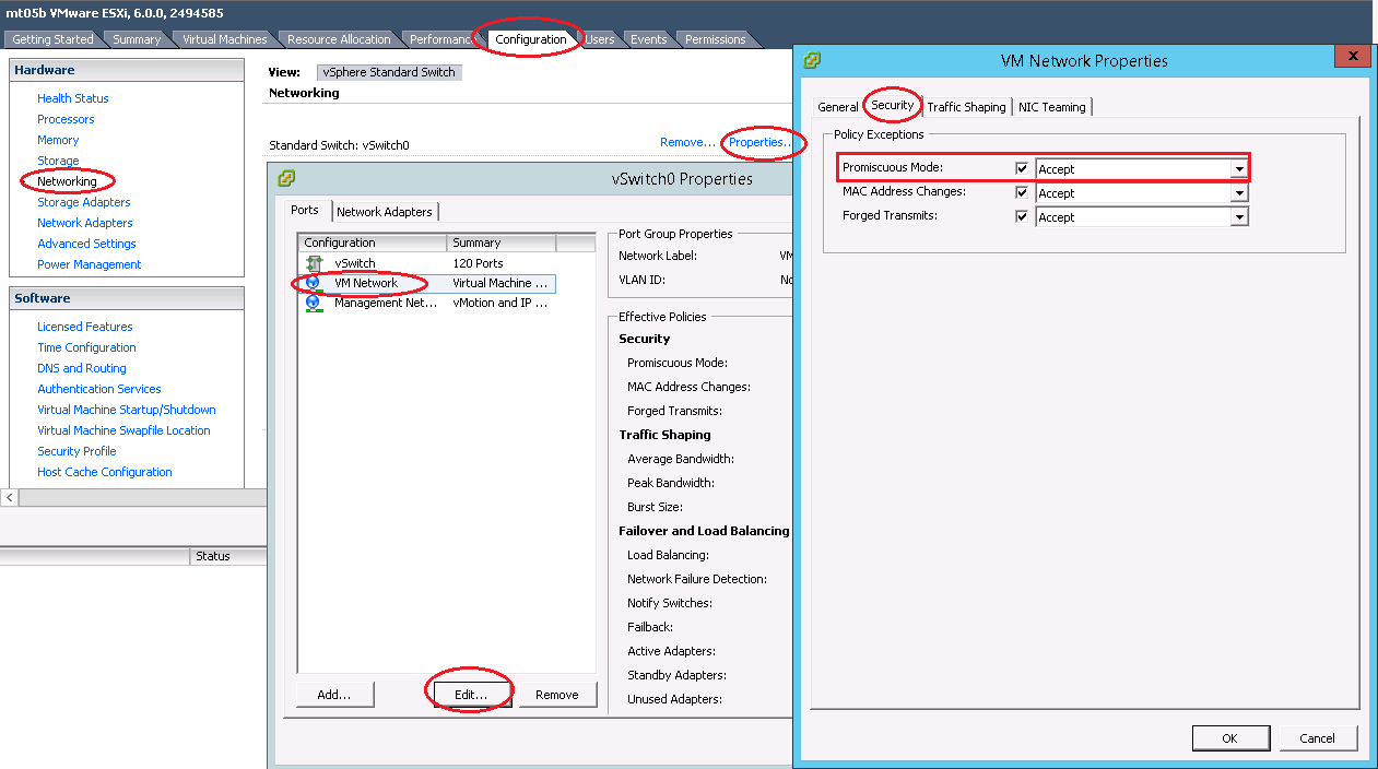
Set Promiscuous Mode to Accept and tick Override. To do this, open the Configuration tab and select Networking. Then click Properties of the vSwitch, choose port group, edit, security, tick the checkbox to override setting and select Accept.
11.2. How to deploy InfraSIM virtual server on different type of platforms
- There are desires to deploy virtual server on different types of hypervisor like:
- VirtualBox
- KVM
- VMWare product, both VMWare vSphere or VMWare workstation
2 possible ways to achieve this:
- Create virtual machine image for corresponding hypervisor beforehand and them import that image onto hypervisors - InfraSIM application is ready in operating system running in virtual machines or containers on top of specified hypervisor or platform. These images are: OVA file for VMWare workstation or vSphere; QCOW2 file for KVM/QEMU; BOX or vagrant/VirtualBox, etc. Below listed some steps on how to deploy these template into different systems:
- Spin-up virtual machines running Ubuntu 64-bit 16.04 OS on desired hypervisor and then install infrasim-compute application. You may also leverage Chef or Ansible to deploy multiple virtual server instances into multiple virtual machines.
11.3. How to generate drive page files
InfraSIM also provides drive page data generating. You can find helpful utility from InfraSIM tools repository. This section walks through steps. Make sure you have access to hardware so boot an OS on target machine you want to simulate, and you have sg3_utils installed. We’ve tried both on Ubuntu 14.04 and 16.04, so they are recommended. First, clone tools to your OS and go to tools/data_generator:
$ cd tools/data_generator
There are 3 ways to generate page files.
Fetch pages from a specific physical drive:
$ sudo python gen_page_utility.py -d /dev/sda -o drive_page.bin
Fetch pages from all physical drives:
$ sudo python gen_page_utility.py -a
It fetches the pages from every physical drive and save them to seperate bin files.
Generate page through json template file
It consists of 3 steps to generate bin file.
First, generate a empty template:
$ python gen_page_utility.py -t -o template.json
Then, modify the content of template.json according to your request and save.
Note: it only supports inquiry page and mode page so far.
Finally, generate page bin file:
$ python gen_page_utility.py -f template.json -o drive_page.bin
11.4. How to simulate another server
InfraSIM also provided many utilities, interfaces for developers to build one simulation solution for a physical node that has not been supported by infraSIM. This sections walk through steps required to build one simulation for one specific server node. While you may find some helpful utilities from InfraSIM tools repository.
Collect SMBIOS
You need access to hardware so boot an OS on target machine you want to simulate. We’ve tried both on Ubuntu 14.04 and 16.04, so they are recommended. Clone tools to your OS, install
dmidecode:$ cd tools/dmidecode-2.12 $ make $ make install
Collect SMBIOS data with the newly installed
dmidecode:$ dmidecode --dump-bin <your-vnode-name>_smbios.bin
Collect BMC emulation data
Unlike to collect SMBIOS data, you only need IPMI over LAN access to collect virtual BMC data. Any environment that can access target machine’s BMC and can run python 2.7 is OK to go. This time, you may leverage
data_generatein tools:$ cd tools/data_generater $ ./gen_emu_utility.py -n <your-vnode-name> auto -H <bmc-ip> -U <bmc-iol-username> -P <bmc-iol-password> -I lanplus
You can specify
-hoption to get more usage.The utility may take seconds to run. After everything is done, you can find a file
node.emu. This includes FRU and SDR of your node.Use SMBIOS data and BMC emulation data
After previous step, you get
<your-vnode-name>_smbios.binandnode.emunow. To contribute this new node type, you need to add these data, then specify the type in infrasim-compute yml configuration.First, add node data, you can:
$ cd /usr/local/etc/infrasim/
$ mkdir <your-vnode-name>
$ mv path/to/<your-vnode-name>_smbios.bin <your-vnode-name>_smbios.bin
$ mv path/to/node.emu <your-vnode-name>.emu
A substitution of first step or a better way is to contribute data to
infrasim-compute/data/with similar structure, and install infrasim-compute again:$ cd infrasim-compute/data $ mkdir <your-vnode-name> $ mv path/to/<your-vnode-name>_smbios.bin <your-vnode-name>_smbios.bin $ mv path/to/node.emu <your-vnode-name>.emu $ cd .. $ sudo python setup.py install
Second, specify
type: <your-vnode-name>in node configuration and start corresponding instance. Refer to customize virtual server and manage node config for detail.
11.5. How to simulate another vPDU - Under construction
InfraSIM provided ServerTech and Panduit PDU simulation initially. InfraSIM also provided many utilities, interfaces for developers to build simulation solution for other physical PDUs. This sections walk through all steps required to build one simulation for other PDU infraSIM doesn’t support yet.
How to retrieve data from physical PDU
If you want to retrieve PDU MIB data, you should have snmpsim installed on your environment.Then run the following command to produce MIB snapshot for the PDU:
# snmprec.py --agent-udpv4-endpoint=<PDU IP address>; --start-oid=1.3.6 --output-file=/path/<target snmprec file>; --variation-module=sql --variation-module-options=dbtype:sqlite3,database:/path/<target pdu database file>,dbtable:snmprecFor more details of how to use snmprec.py, please go to section Producing SNMP snapshots at snmpsim home page for more help.
How to simulate physical PDU in InfraSIM
Once you retrieved data from physical PDU, the next step is to add a virtual PDU in InfraSIM for this physical server. The following steps will guide you how to do:
- Create a directory named PDU name at idic/vpdu
- Create a directory data at idic/vpdu/<PDU name>/data, and copy the data you get from physical server into data directory.
- Copy .config and Makefile into idic/vpdu/<PDU name>, and update target name in Makefile and .config
- Clone vpduserv, and implement the new pdu logic based on vendor’s PDU spec.
11.6. How to integrate RackHD with InfraSIM
RackHD is an open source project that provides hardware orchestration and management through APIs. For more information about RackHD, go to http://rackhd.readthedocs.io.
The virtual hardware elements(virtual compute node, virtual PDU, virtual Switch) simulated by InfraSIM can be managed by RackHD.
The following picture shows the deployment model for the integration of InfraSIM and RackHD:
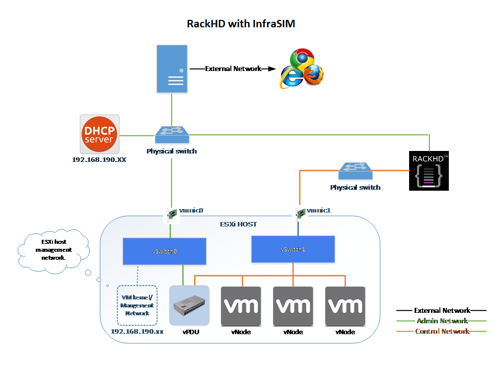
The networking connection between InfraSIM and RackHD is shown below:
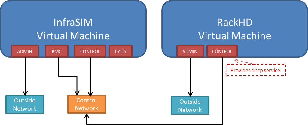
Please follow below steps to setup the entire environment. After that, RackHD can discover and manage the virtual server and virtual PDU just as the real physical server and PDU. Note that in the example, virtual machines are spinned up on VMWare workstation. Configuration is similiar on other platforms.
Enable VT-d in BIOS on Physical Server as in chapter 11.1.
Create two virtual machines(for InfraSIM/RackHD respectively) inside VMWare workstation, or use ova images built by InfraSIM and RackHD groups.
Create a Custom network(name it
VMnet2here) in VMWare workstation with configuration below: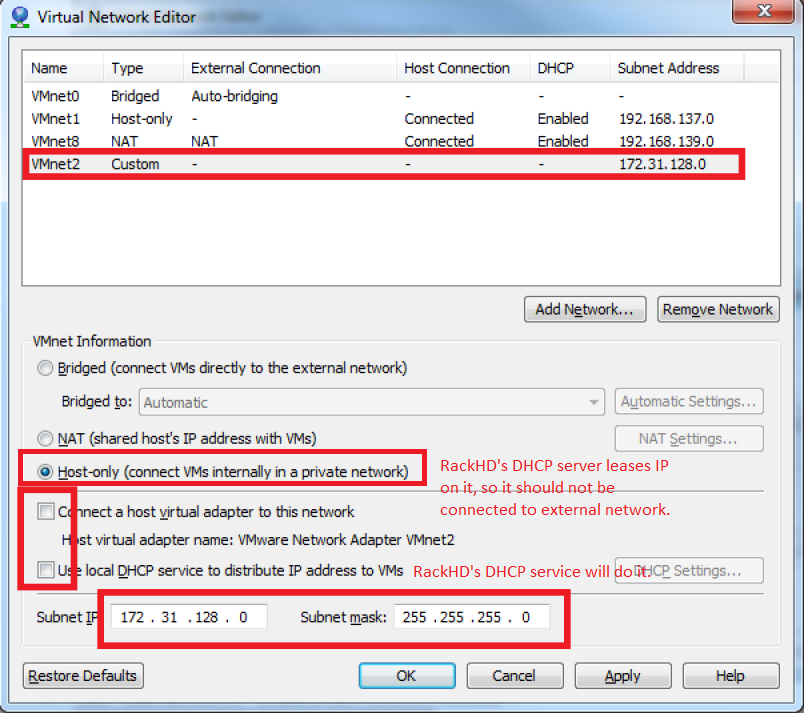
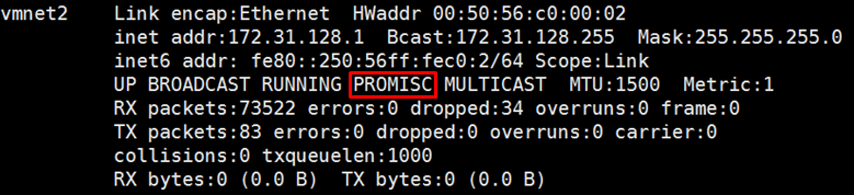
If you are using VMWare workstation linux version, you might need to change some settings in the OS running workstation and the vm running InfraSIM.
In the OS running VMWare workstation, turn on promiscuous mode for virtual nic adapter
VMnet2:... sudo chmod a+rw /dev/vmnet2 sudo ifconfig vmnet2 promisc ...
Turn on nested option for
kvm_intelin InfraSIM vm:... sudo rmmod kvm_intel sudo modprobe kvm_intel nested=1 ept=1 ...
In the VMWare workstation, choose the InfraSIM vm and check Virtualization Intel VT-x/EPT or AMD-V/RVI in VM settings.
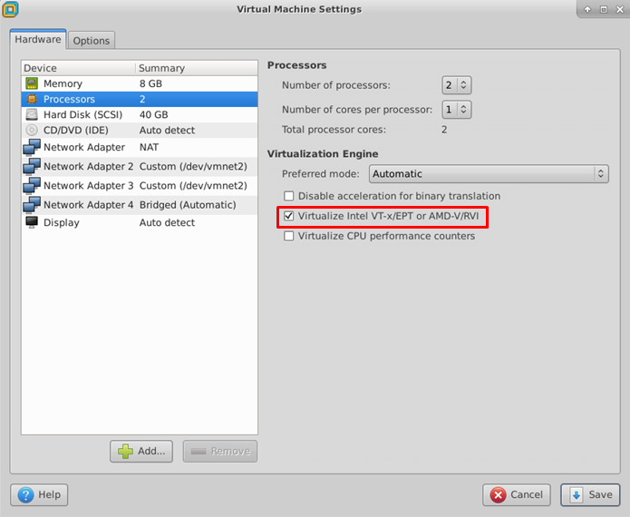
Restart VMWare workstation and the vms.
Configure network connection for InfraSIM virtual machine:
In virtual machine settings, create network adapters:
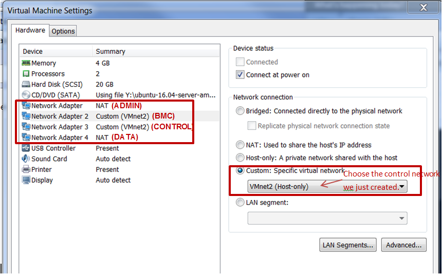
Modify
/etc/network/interfacesfor theBMCandCONTROLnetworks:... auto <BMC ifname> iface <BMC ifname> inet dhcp post-up ifconfig <BMC ifname> promisc auto <CONTROL ifname> iface <CONTROL ifname> inet dhcp post-up ifconfig <CONTROL ifname> promisc ...
<BMC ifname> and <CONTROL ifname> are the names of infrasim vm’s BMC and CONTROL network adapters. Check
ifconfigto get the ifname.- Create a network bridge and add
CONTROLinterface to the bridge referring to How to create a bridge.
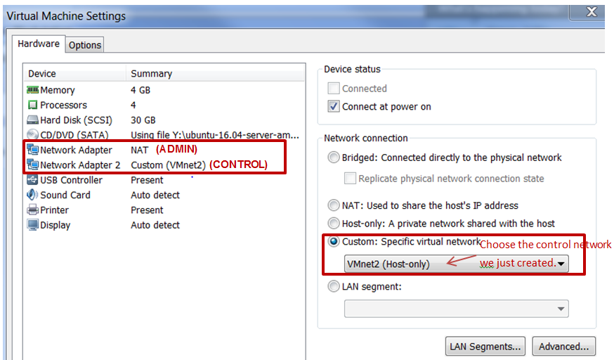
Configure network connection for RackHD virtual machine:
RackHD server should be configured with as least two networks,
"Admin network"and"Control Network".- “Admin Network” is used to communicate with external servers
- “Control Network” is used to control the virtual servers.
- In virtual machine settings, create network adapters:
In
/etc/network/interfaces, configure theCONTROLnetwork interface to static:... auto <CONTROL ifname> iface <CONTROL ifname> inet static address 172.31.128.1 netmask 255.255.240.0 ...
Check
ifconfigto find <CONTROL ifname> forCONTROLnetwork and fill in the commands above.Install RackHD from source code. Please refer RackHD document to setup the RackHD Server.
Install InfraSIM from source code.
Please refer Installation in this document to install InfraSIM.
Modify yaml file to add BMC binding and change qemu network interface to bridge mode:
...
    networks:
        -
            network_mode: bridge
            network_name: <bridge_name>
            device: e1000
...
bmc:
    interface: <BMC ifname>
...
Note
The default yaml file is stored at ${HOME}/.infrasim/.node_map/default.yml.
Start RackHD service and InfraSIM service.
After you setup the environment successfully, you can get the server information and control the servers by RackHD APIs. More information about how RackHD APIs communicate with the compute server and PDU, Please refer http://rackhd.readthedocs.org/en/latest/rackhd/index.html#rackhd-api
11.7. How to hotplug devices
InfraSIM incorporate QEMU’s hotplug interface via QMP or HMP to provide device hotplug. This function is exposed via QEMU monitor, while a feature called infrasim monitor is under construction for easy use.
Prerequisites
You need to check these prerequisites before any hotplug operations:
- From source code’s perspective, the device class implements TYPE_HOTPLUG_HANDLER, and
with well implements on
plugandunplughandler. - From QEMU runtime’s perspective, see if option
-monis specified. Eithermode=controlormode=readlinehas approach to do hotplug operation.
- From source code’s perspective, the device class implements TYPE_HOTPLUG_HANDLER, and
with well implements on
Hotplug Example
Here is an example on how to do hotplug on QMP. A basic principle is to define the specific device, then mount it as a QEMU device. You can learn how to compose the QMP command via QMP schema. Further more, this article tells you how to write your own QMP command. Another tip is how to talk with QEMU monitor: write your own code to connect the UNIX or INET socket, or use unix
nccommand:# "C" is for client request # "S" is for server reply # Replies are omitted in this example # Issue the qmp_capabilities command, so that QMP enters command mode C: { "execute": "qmp_capabilities" } S: ... # Issue the blockdev-add to define one block device # this command could be changed in future version C: { "execute": "blockdev-add", "arguments": { "bus": "scsi0" "unit": "5" "options": { "id": "scsi0-0-5-0", "driver": "qcow2", "file": { "driver": "file", "filename": "/home/infrasim/tmp5.img" } } } } S: ... # Issue the device_add to mount device on bus C: { "execute": "device_add", "arguments": { "driver": "scsi-hd", "id": "tmpscsihd5", "product": "PX04SMB160", "ver": "AM04", "scsi-id": "5", "bus": "scsi0.0", "drive": "scsi0-0-5-0", "channel": "0", "lun": "0", "serial": "26E0B392TD2P", "wwn": "5764611469732290481" } } S: ... # Delete device first C: { "execute": "device_del", "arguments": { "id": "tmpscsihd5" } } S: ... # Clear the block devicev # this command could be changed in the future too C: { "execute": "x-blockdev-del", "arguments": { "id": "scsi0-0-5-0" } } S: ...Here’s another example on how to do hotplug on HMP. This example do exactly the same things with above QMP example. HMP schema indicates how to specify the parameters:
(qemu) drive_add scsi0:5 file=/home/infrasim/tmp5.img,
       format=qcow2,id=scsi0-0-5-0,if=none
...
(qemu) device_add scsi-hd,product=PX04SMB160,ver=AM04,
       scsi-id=5,bus=scsi0.0,drive=scsi0-0-5-0,channel=0,
       serial=26E0B392TD2P,wwn=5764611469732290481,lun=0,
       id=tmpscsihd5
...
(qemu) device_del tmpscsihd5
...
(qemu) drive_del scsi0-0-5-0
...