7. User Guide
This chapter will deep to the InfraSIM usage of deploying large scale virtual infrastructure. If simply virtual compute nodes or small scale infrastructure already works, you can refer to Quick Start to get that setup.
Many functionalities described in this chapter, such as vRackSystem for InfraSIM deployment and virtual PDU are supported only on top of VMWare vSphere Client(ESXi) as of now. In Build, Package and Deployment chapter, we describe how to build and deploy virtual compute node on top of KVM, Docker, Virtual Box, VMWare workstation and ESXi.
Notice: Before you start this chapter, please follow the instructions in Build vNode and vPDU to build the vNode and vPDU OVA images, which can be deployed on ESXi.
Index of User Guide:
- Setup InfraSIM on ESXi
- How to install ESXi on physical server
- Deploy and control vNode
- Deploy and control vPDU
- Access vBMC data
- vSwitch setup
- vRackSystem User Manual
- Test InfraSIM
7.1. Setup InfraSIM on ESXi
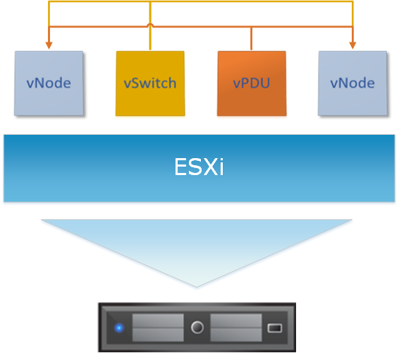
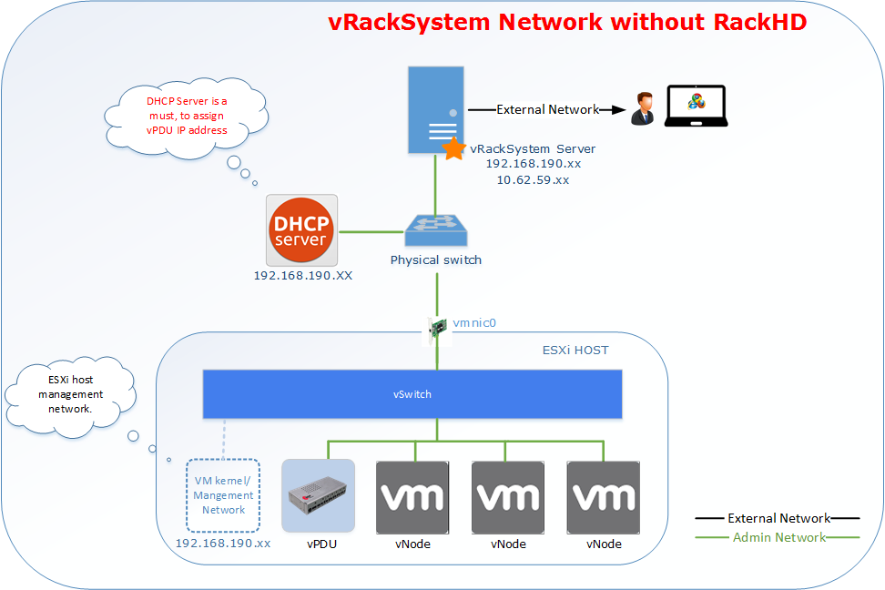
Below diagram shows virtual infrastructure deployed on one ESXi instance. Please follow the step by step manual in the following sections to setup this environment.
7.1.1. Install ESXi on Physical Server
- Requirement of physical server
The physical server must support ESXi 6.0 and it should be allocated at least 3 NIC ports. The first NIC port is used for the admin network connection. The second and third NIC ports are used for control network connection(The second NIC is required. The third NIC is optional). The fourth NIC port is used for data network connection (optional).
- Setting Up Network Connections
You must have IP addresses for the physical servers in the test environment to be used to configure the VMKernal port of ESXi and called as ESXi_Admin_IP.
- Allocate or reserve a static IP address from the Lab admin.
- Connect the server’s admin NIC ports into the Lab network.
- To set up a multiple server environment, connect Port C1 on each server by using an Ethernet switch.
- Install ESXi 6.0
From the VMWare web site, a 60-day free trial version is available after user registration.
- Go to https://my.vmware.com/web/vmware/details?downloadGroup=ESXI600&productId=490&rPId=7539
- Download the VMWare vSphere Hypervisor 6.0 (ESXi6.0) ISO image.
- Install ESXi 6.0 on each physical server.
- Configure the static IP address ESXi_Admin_IP on first NIC port.
- Set the Administrator user name by using the format <User Name>.
- Set the Administrator Password by using the format <Password>.
- Installing VMWare vSphere Client (Remote System)
- Go to the VMWare web site.
- Download the VMWare vSphere Client.
- Install the client on a remote system that can connect to the physical servers.
- Configuring the Virtual Network
Launch the vSphere client and connect to ESXi on the physical server by using ESXi_Admin_IP.
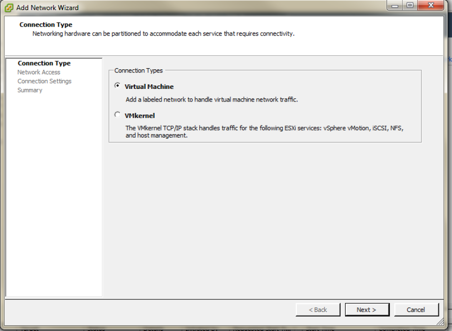
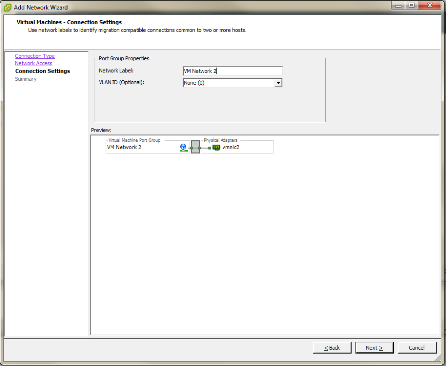
On the Configuration tab, click Add Networking, to create the Control vSwitch. In the example, the network label is “VM Network 2”.

Select Virtual Machine
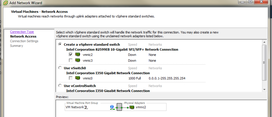
Select Create a vSphere standard switch > vmnic2.
In the Network Label field, type port group name on target switch.
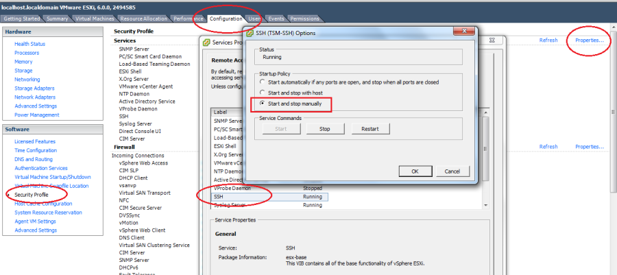
Enable the SSH service on ESXi. To do this, open the Configuration tab and select Security Profile. Then select SSH and click Properties to set the SSH (TSM-SSH) to start and stop manually.
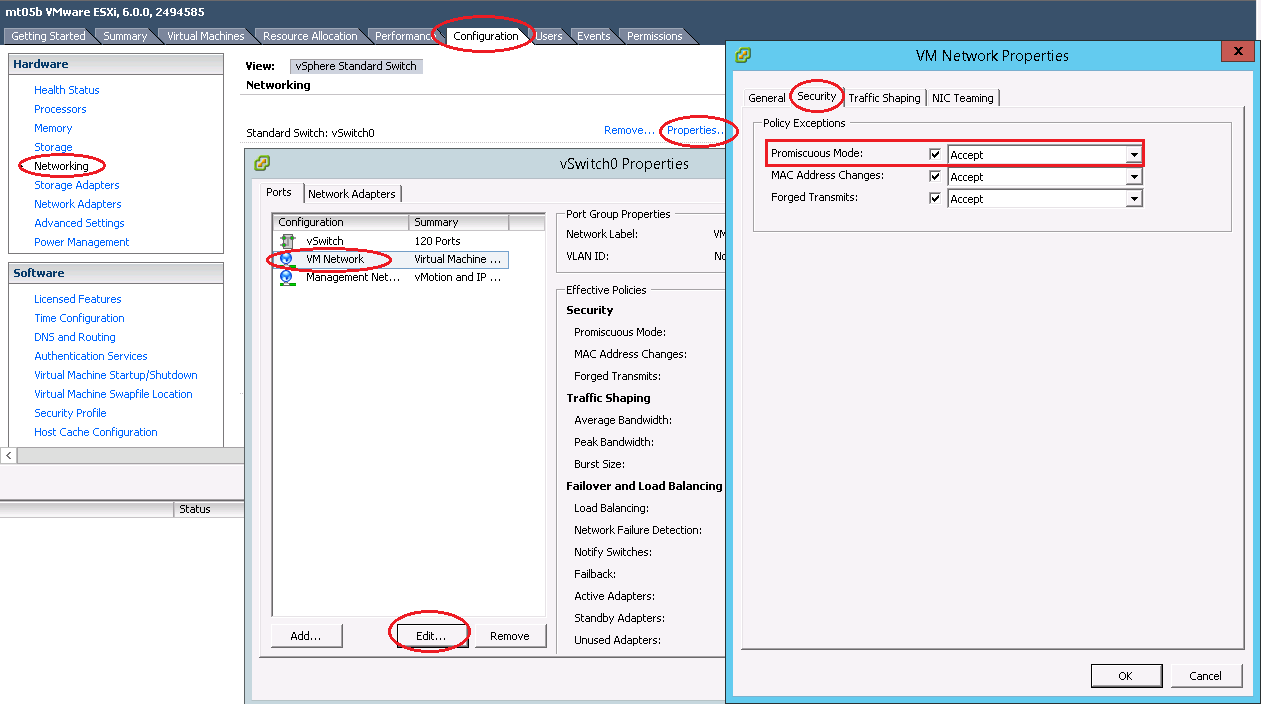
IMPORTANT NOTE: Set Promiscuous Mode to Accept and tick Override. To do this, open the Configuration tab and select Networking. Then click Properties of the vSwitch, choose port group, edit, security, tick the checkbox to override setting and select Accept.
7.1.2. vNode Deployment and Control
- Deploy virtual Compute Node to ESXi manually
The virtual compute node OVA image is a standard image that can be deployed to ESXi directly.
IMPORTANT NOTE: Login to the ESXi server through SSH and echo by issuing the “vhv.enable = “TRUE”“ command to the /etc/vmware/config file. This command enables nested ESXi and other hypervisors in vSphere 5.1 or higher version. This step only needs to be done once by using the command: echo ‘vhv.enable = “TRUE”’ >> /etc/vmware/config.
- Deploy virtual compute node by vRackSystem
Please access vRackSystem User Manual for more information.
7.1.3. vPDU deployment and control
vPDU deployment
- Deploy vPDU Manually
The vPDU is part of the vCompute node. The vPDU has two network adapters. One is connected to the management network and used to communicate with the ESXi host. The other is connected to the internal network and used to communicate with the application you are testing.
Get the vPDU OVA file that you built when you deployed the virtual compute nodes.
Deploy the vPDU image on the vSphere client by click File -> Deploy OVF Template
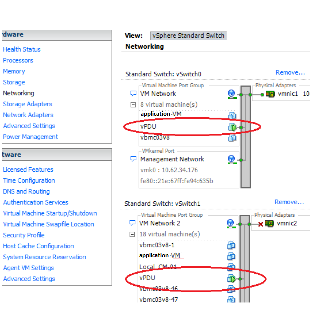
- Configure the vPDU network adapters as shown in the following picture.
Start the vPDU VM.
Click Open console to see the vPDU IP address.
- Deploy vPDU by vRackSystem
Please access vRackSystem User Manual for more information.
Configuring the vPDU
Configure vPDU Manually
On a server that has a network connection to the vPDU, use the SSH client to log in to the vPDU.:
ssh <ip address> -p 20022
When the (vPDU) prompt displays, specify the ESXi host information.:
config esxi add <esxi host ip> <esxi host username> <esxi host password>
config esxi update host <esxi host ip>
config esxi update username <esxi host username>
config esxi update password <esxi host password>
Note: Use config esxi list to verify the settings.
Configure the eth1 IP address that is used to communicate with ESXi host.:
ip set eth1 <ip address> <net mask>
Note: Use ip get eth1 and ip link eth1 status to verify the settings.
- Configure mappings between the VM and the vPDU port.
Add mapping between the VM and the vPDU port.:
map add <datastore name> <VM Name> <vPDU number> <vPDU port>
List the current mappings on vPDU.:
map list
Delete a VM from a datastore:
map delete <datastore name> <VM Name>
Update an existing mapping between VM and vPDU port:
map update <datastore name> <VM Name> <vPDU number> <vPDU port>
Delete all VMs in a datastore:
map delete <datastore name>
Restart the vPDU service:
vpdu restart
- Configure vPDU by vRackSystem
Please access vRackSystem User Manual for more information.
Retrieve vPDU Service
You can use SNMP commands to retrieve information about the PDU device:
snmpwalk -v2c -c ipia <vPDU IP Address> HAWK-I2-MIB::invProdFormatVer
snmpwalk -v2c -c ipia <vPDU IP Address> HAWK-I2-MIB::invProdSignature
snmpwalk -v2c -c ipia <vPDU IP Address> HAWK-I2-MIB::invManufCode
snmpwalk -v2c -c ipia <vPDU IP Address> HAWK-I2-MIB::invUnitName
snmpwalk -v2c -c ipia <vPDU IP Address> HAWK-I2-MIB::invSerialNum
snmpwalk -v2c -c ipia <vPDU IP Address> HAWK-I2-MIB::invFwRevision
snmpwalk -v2c -c ipia <vPDU IP Address> HAWK-I2-MIB::invHwRevision
Verify the password
You must verify the password before you can control the vPDU because the password is used for communication:
snmpset -v2c -c ipia <vPDU IP Address> HAWK-I2-MIB::pduOutPwd.1.[Port] s [Password]
The following table describes the information to include.
Option Description Port The vPDU port number (Range: 1-24) Password The password you set for a specific port Power Up and Booting the vPDU
Power on, power off, or reboot the vPDU:
snmpset -v2c -c ipia <vPDU IP Address> HAWK-I2-MIB::pduOutOn.1.[Port] i [Action]
The following table describes the information to include.
Option Description Port The vPDU port number (Range: 1-24) Action On, off, or reboot Retrieving the vPDU Port State Get the state of the vPDU port:
snmpget –v2c –c ipia 172.31.128.244 HAWK-I2-MIB::pduOutOn.1.[Port]
7.1.4. Access vBMC Data
This section explains how to access the vBMC information and how to change the boot option of the virtual node. You can access information from the virtual BMC, change sensor values, configure the sensor mode, add a SEL entry for a particular sensor, and monitor the virtual node BIOS/iPXE/OS/ runtime output instead of VNC.
- Accessing BMC Static Data via ipmitool command
Communicate with the BMC by using the ipmitool command. ipmitool commands for accessing BMC data have the following format:
ipmitool –I <interface> –H <address> –U <username> –P <password> <expression>
The following table describes the information to include.
Option Description -I <interface> The IPMI interface to use. Use -I lanplus* for commands that are described in this section. -H <address> The IP address of the BMC. –U <username> Admin user name. –P <password> Admin password. <expression> - The operation to perform. For example.
sensor: operate the available sensors
fru : operate the available FRUs
sdr: check the sdr info
raw: send raw command to virtual BMC
chassis: power off/power on/set bootdev of the system
sel: check/clear the sel entries in the vBMC
lan: check lan information of the vBMC
User: check user information
- Accessing Dynamic Sensor Data by IPMI_SIM
- InfraSIM support to access the dynamic sensor data by IPMI_SIM, it includes below functionalities:
- Dynamic sensor reading
- Ability to change sensor value
- Generate sensor values across sensor thresholds
- Inject SELs for the particular sensors.
Please follow below steps to play with InfraSIM IPMI_SIM
- Enter IPMI_SIM by below command.
If you are on the top of the application server, use:
ssh vbmc_ip -p 9300
If you are on the top of vbmc server, use:
ssh localhost -p 9300
Enter help to check all the commands supported.:
# help
Below tables shows the detail information about each command.
Commands Description sensor info Get all the sensor information. sensor mode set <sensorID> <user> - Set the sensor mode to the user mode.
- Leaves the sensor reading as it currently is until instructed otherwise
sensor mode set <sensorID> <auto> - Set the sensor mode to the auto mode.
- Changes the sensor reading to a random value between the lnc and unc thresholds every 5 seconds.
sensor mode set <sensorID> <fault> <lnr | lc | lnc | unc | uc | unr > - Set the sensor mode to the fault mode.
- Changes the sensor reading to a random value to cause a particular type of fault as instructed (lnr, lc, lnc, unc, uc, unr)
lower non-recoverable threshold
lower critical threshold
lower non-critical threshold
upper non-critical threshold
upper critical threshold
upper non-recoverable threshold
sensor mode get <sensorID> Get the current sensor mode. sensor value set <sensorID> <value> Set the value for a particular sensor.. sensor value get <sensorID> Get the value of a particular sensor. sel set <sensorID> <event_id> <’assert’/’deassert’> - Inject(Assert/Deassert) a sel error.
- You can use the sel set command to add a SEL entry for a particular sensor.
sel get <sensorID> - Get the sel error for a sensor.
- You can use the sel get command to get the available events for a particular sensor.
You can also get the BMC data by IPMI command. For example, have a check on fan speed and check the sel list by:
# ipmitool -I lanplus -U admin -P admin -H <vm ip address> sdr type fan
# ipmitool -I lanplus -U admin -P admin -H <vm ip address> sel list
7.1.5. vSwitch Setup
You can implement the vSwitch component of InfraSIM by deploying the Cisco Nexus 1000v switch on the ESXi host.
For more information on downloading and using Cisco Nexus 1000v switch, refer to http://www.cisco.com/c/en/us/products/switches/nexus-1000v-switch-vmware-vsphere/index.html.
7.2. vRackSystem
This sections describes using infraSIM utility vRackSystem to do large scale infrastructure deployment and management on top of ESXi.
7.2.1. Overview
vRackSystem is web-based system designed to efficiently build and manage virtual infrastructure, including below features:
- Manage ESXi resources
- Deploy the virtual nodes (vNode and vPDU) built by InfraSIM.
- Control(Power on / Power Off / Reset / Delete) the virtual nodes and virtual PDU.
- Bind vPDU outlets with virtual nodes (vNode and vPDU).
- vNodes customization (Customize sub-component, processor, memory, Drive and NIC).
- RackHD integration and testing
RackHD (https://github.com/RackHD) is an open source project that provides hardware orchestration and management through APIs. More information can be found at http://rackhd.readthedocs.org/en/latest/.
7.2.2. Server Requirements
vRackSystem Prerequisite
- Linux server with ssh installed and ssh public key generated
- Direct network connection to all the ESXi hosts to be managed
- External network connection to be accessible as a Web server.
The following diagrams illustrate vRackSystem networks.
7.2.3. Setting up Environment
Install Python version 2.x, except version 2.7.9:
sudo apt-get install python
sudo apt-get install python-pip
sudo apt-get install python-dev
sudo apt-get install python-setuptools
Check whether Python was successfully installed and that the version is correct:
python --version
- Install the VMWare ovftool file.
Download the VMWare OVF bundle, version 4.1.0 for Linux. Go to https://my.vmware.com/group/vmware/details?productId=491&downloadGroup=OVFTOOL410 (4.1.0 version, for Linux).
Copy the bundle file to the vRackSystem server.
Install the OVF tool:
sudo bash VMware-ovftool-4.1.0-2459827-lin.x86_64.bundle
Install MySQL:
sudo apt-get install mysql-server
sudo apt-get install python-mysqldb
- Import a database.
Copy the existing databases file (vracksystem.sql) from XXX to your server.
Enter your database:
mysql -u <your mysql account> -p
Enter your MySQL password.
Import the databases file:
source /path/to/vracksystem.sql
Clone the vRackSystem code from github repository: https://github.com/InfraSIM/vracksystem
Change vracksystem/ova/ folder privilege to 777.
cd vracksystem
sudo chmod -R 777 ova/
Install the Python packages:
cd vracksystem
sudo pip install -r requirements.txt
- Update the database connection information.
Use your MySQL account username and password in the /vracksystem/AutodeployUI/settings.py file.
DATABASES = {
     'default': {
         'ENGINE': 'django.db.backends.mysql',
         'NAME': 'AutoDeployUI',
         'USER': '<your mysql account>',
         'PASSWORD': '<your mysql password>',
         'HOST':'localhost',
     }
 }
Copy the OVA images, including RackHD OVA images, vNode and vPDU images, to the /vracksystem/ova/ directory.
Start vRackSystem:
cd vracksystem
python manage.py runserver 0.0.0.0:<port>
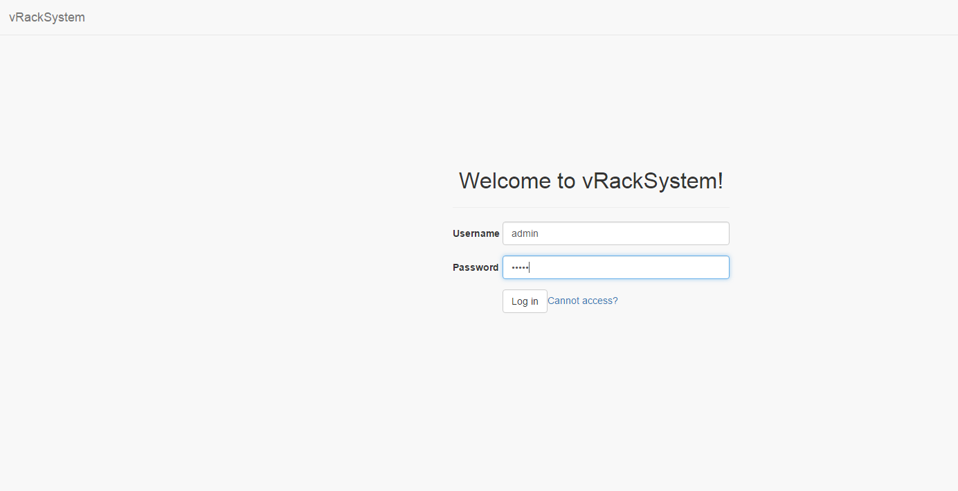
To access the vRackSystem GUI go to http://<server IP>:<port>/login, use account admin/admin to login.
7.2.4. User Manual
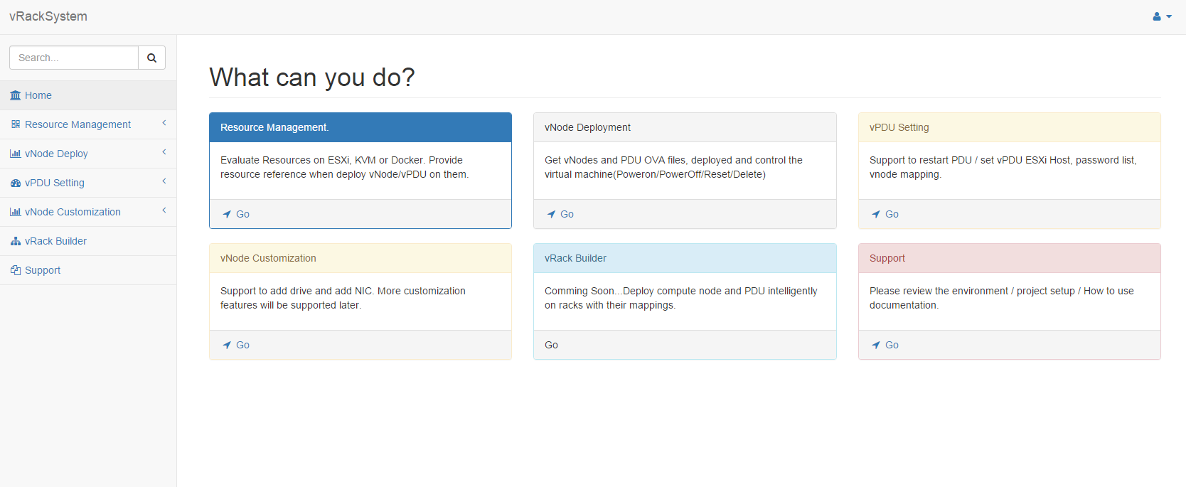
Features Introduction:
- Resource Management. Currently only supported with ESXi.
- vNode/vPDU deployment and control.
- vPDU Settings
- vNode Customization. Support to customize Drive/NIC to a virtual machine.
- Support
Step by Step Manual:
- Login the system by accessing http://<server IP>:<port>/login.
- Login the system with account admin/admin.
- Contact us when you cannot access the system.
- Main page.
- After login, you can see the main page.
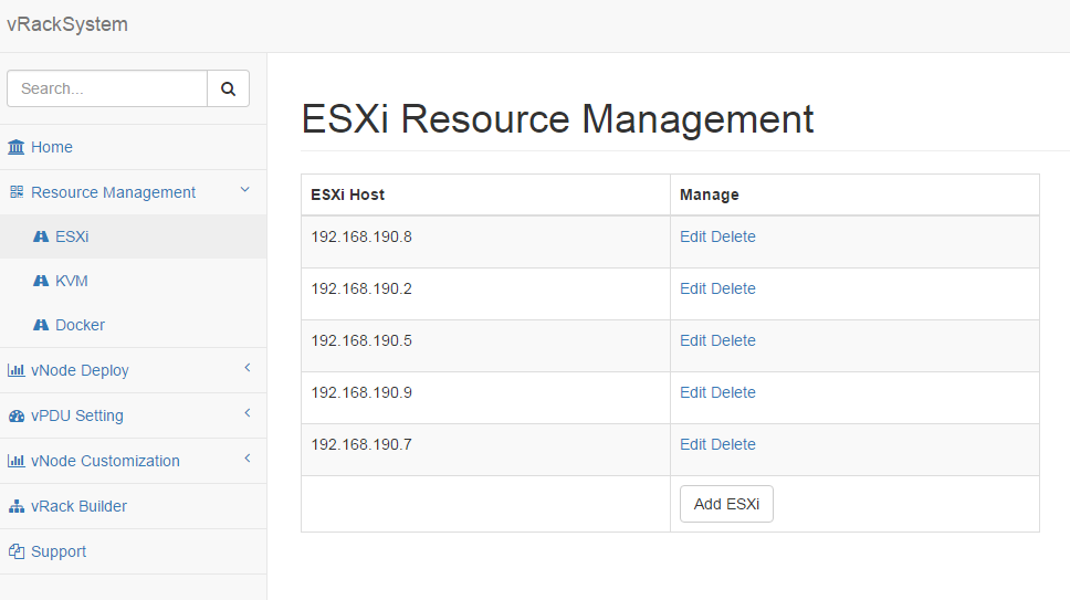
- Resource Management.
- Go to “Resource Management” -> “ESXi”.
- You can Add / Edit / Delete an ESXi resource.

- vNode/vPDU deployment and control.
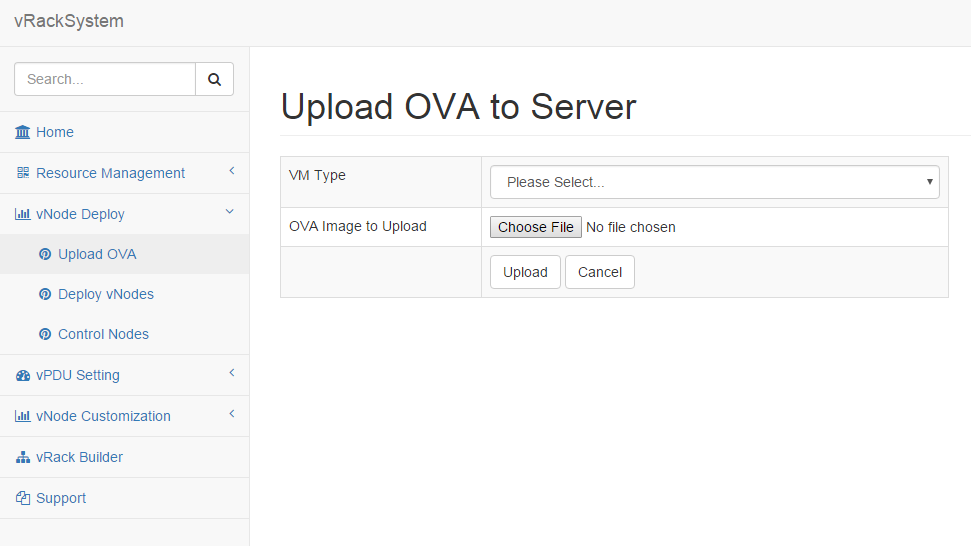
- Go to “vNode Deploy” -> “Upload OVA” to upload an OVA image to vRackSystem Server.
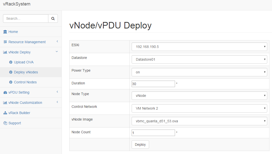
- Go to “vNode Deploy” -> “Deploy vNodes” to deploy vNodes or vPDU. The process is as below.
Select an ESXi.
The “Datastore” information will be loaded automatically.
Select the “Power Type”. It means the power status after the deployment of the nodes.
Input the duration, it means interval between two nodes deployment.
Choose a “Node Type”. If you choose vNode, you need to select the Control Network. Otherwise, Control Network is not a must.
The “vNode Image” on vracksystem will be automatically loaded. If there are no OVA image that you need, please go to “vNode Deploy” -> “Get OVA” to download.
Input the “Node Count” you want to deploy.
Click “Deploy” to start the deploy process.
- Go to “vNode Deploy” -> “Control vNodes” to control the vNodes. The process is as below.
Select an “ESXi Host”.
The hardware information of the ESXi host and also the virtual machines on the ESXi will display automatically.
You can choose several virtual machine to do “Power On”, “Power Off”, “Delete”, “Reset”.
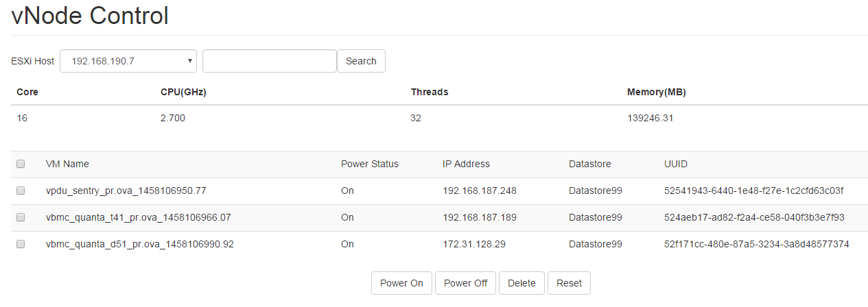
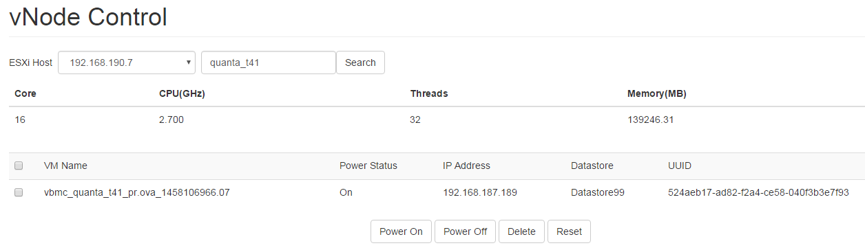
Also you can input some text in the search box to search the virtual machine whose name contains the search keyword.
- vPDU Setting.
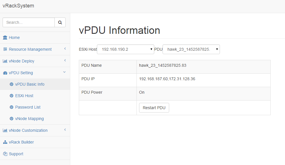
- Go to “vPDU Setting” -> “vPDU Basic Info” to get the PDU basic information. The process is as below.
- Select an “ESXi Host”.
- The PDU will be automatically loaded. Then choose a “PDU”.
- After you choose a PDU, you will get the name, IP and power status of the PDU.
- You can restart the PDU by click “Restart PDU”.
- Go to “vPDU Setting” -> “ESXi Host” to check or set the PDU ESXi Host information. The process is as below.
Select an “ESXi Host”.
The PDU will be automatically loaded. Then choose a “PDU”.
After you choose a PDU, the ESXi Host information will list there.
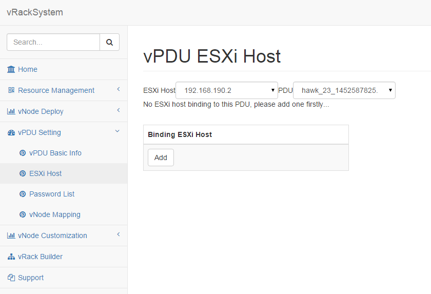
If there’s no “ESXi Host” bound there, please add one.
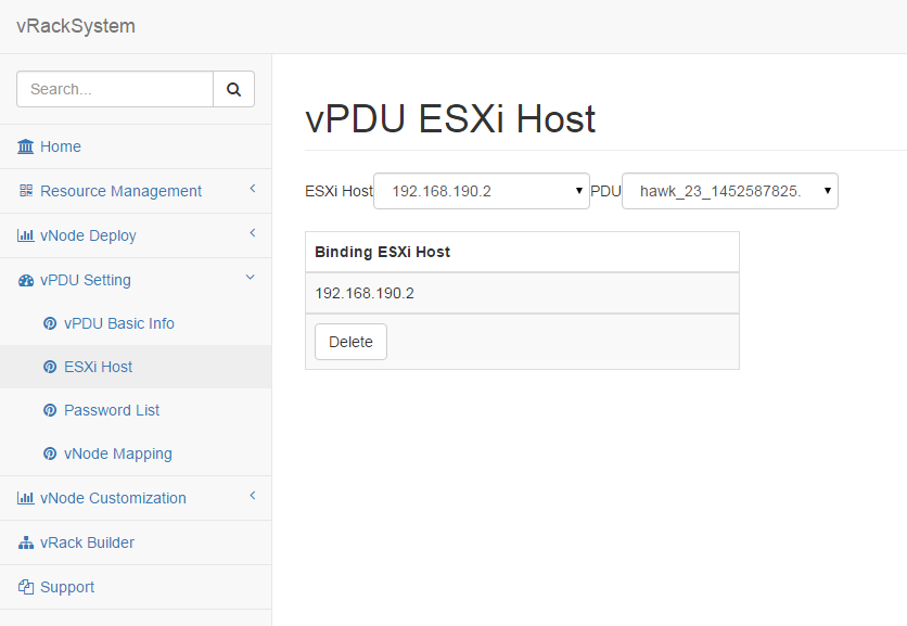
If there’s already one “ESXi Host” there, you can delete it.
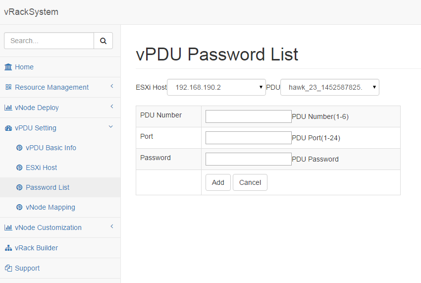
- Go to “vNode Deploy” -> “Password List” to check and set the PDU password. The process is as below.
Select an “ESXi Host”.
The PDU will be automatically loaded. Then choose a “PDU”.
After you choose a PDU, the existing password list will be loaded automatically.
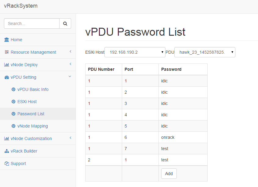
You can Add a new password for a PDU port.
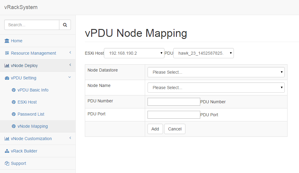
- Go to “vNode Deploy” -> “vNode Mapping” to check and set the PDU <-> Node mapping. The process is as below.
Select an “ESXi Host”.
The PDU will be automatically loaded. Then choose a “PDU”.
After you choose a PDU, the existing node mapping list will be loaded automatically.
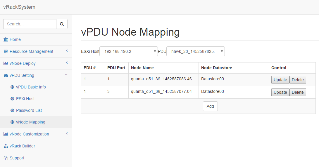
You can “Add” / “Update” / “Delete” mappings.
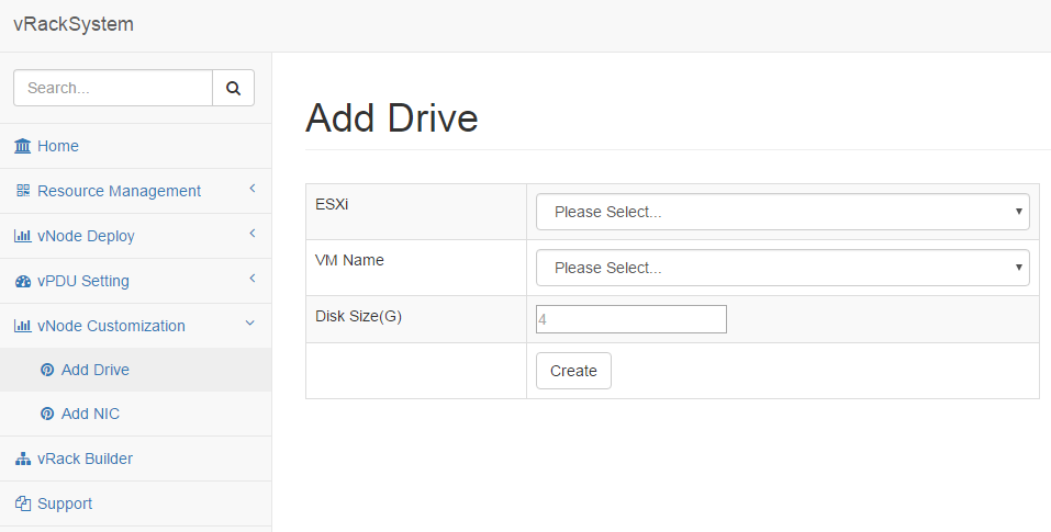
- vNode Customization.
- Go to “vPDU Customization” -> “Add Drive” to add a drive for a virtual machine. This feature will support after SCSI drive supported. The process is as below.
Select an “ESXi Host”.
The virtual machine on the ESXi host will be automatically loaded. Then choose a virtual machine.
Input an Integer disk size.
Click “Add” to add a drive for the virtual machine.
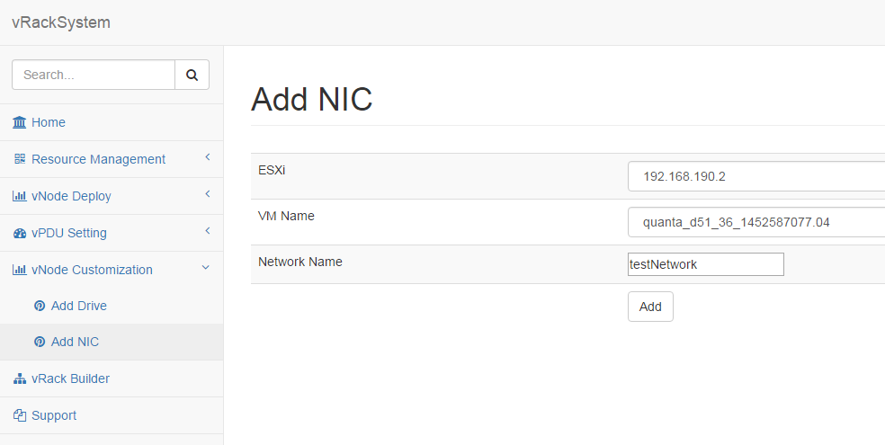
- Go to “vPDU Customization” -> “Add NIC” to add a NIC for a virtual machine. The process is as below.
Select an “ESXi Host”.
The virtual machine on the ESXi host will be automatically loaded. Then choose a virtual machine.
Input NIC name you want to add.
Click “Add” to add a drive for the virtual machine.
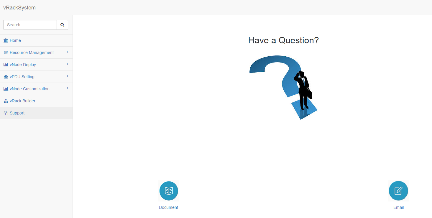
- Support.
- Go to “Support” to find support when you encounter issues.
Click “Document” to read our release document.
Click “Email” to email our with your comments and suggestions, or questions.
7.2.5. APIs
- vRackSystem exposed a set of Restful APIs for easier integration with external systems and automation test. All of the Restful APIs are encapsulated by SwaggerUI, all the Restful APIs are visible in one web page. The access steps are as below:
REST APIs Introduction
- GET /api/v1/esxi/
Get all the esxi list maintain in vRackSystem.
- POST /api/v1/esxi/
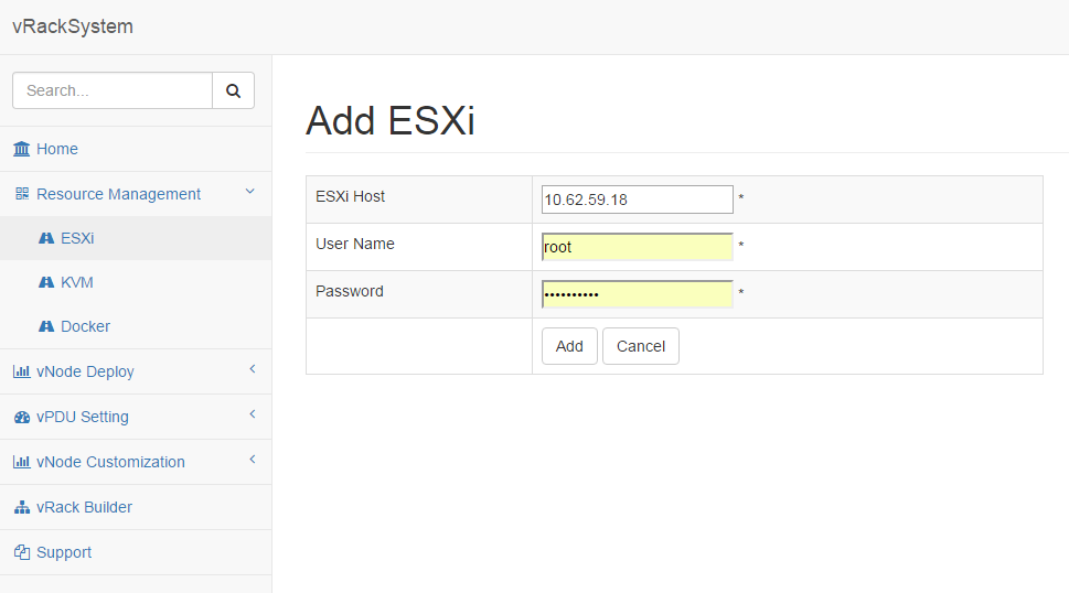
Add an ESXi server for vRackSystem to maintain. Need to provide ESXi host IP, username and password. After adding ESXi host, vRackSystem will assign a unique id for each ESXi host. This id will be used as index of many other APIs.
Arguments Description esxiIP ESXi Host IP address username ESXi Host username password ESXi Host password
- GET /api/v1/esxi/{id}/
Get the specific ESXi host information.
Arguments Description id ESXi Host id
- PUT /api/v1/esxi/{id}/
Update the information of one specific ESXi host. All the fields are needed.
Arguments Description id ESXi Host id esxiIP ESXi Host IP address username ESXi Host username password ESXi Host password
- PATCH /api/v1/esxi/{id}/
Update the information of one specific ESXi host. Not all of the fields are needed.
Arguments Description id ESXi Host id esxiIP ESXi Host IP address username ESXi Host username password ESXi Host password
- DELETE /api/v1/esxi/{id}/
DELETE one specific ESXi host.
Arguments Description id ESXi Host id
- GET /api/v1/esxi/{id}/getvms
Get the VMs in the specific ESXi host.
Arguments Description id ESXi Host id
- POST /api/v1/esxi/{id}/getvminfo
Get the detail information of a virtual machine in the specific ESXi host.
Arguments Description id ESXi Host id name virtual machine name in ESXi host
- POST /api/v1/esxi/{id}/poweronvm
Power on a virtual machine in the specific ESXi host.
Arguments Description id ESXi Host id name virtual machine name in ESXi host
- POST /api/v1/esxi/{id}/poweroffvm
Power off a virtual machine in the specific ESXi host.
Arguments Description id ESXi Host id name virtual machine name in ESXi host
- POST /api/v1/esxi/{id}/resetvm
Reset a virtual machine in the specific ESXi host.
Arguments Description id ESXi Host id name virtual machine name in ESXi host
- POST /api/v1/esxi/{id}/destroyvm
Delete a virtual machine in the specific ESXi host.
Arguments Description id ESXi Host id name virtual machine name in ESXi host
- GET /api/v1/esxi/{id}/hardware
Get the hardware information of a specific ESXi host.
Arguments Description id ESXi Host id
- GET /api/v1/esxi/{id}/datastores
Get the data store information of a specific ESXi host.
Arguments Description id ESXi Host id
- GET /api/v1/esxi/{id}/networks
Get the networks information of a specific ESXi host.
Arguments Description id ESXi Host id
- POST /api/v1/esxi/{id}/deploy
Deploy a virtual nodes(vNode and vPDU) to a specific ESXi host.
Arguments Description id ESXi Host id datastore The datastore that the node will deploy to power The power type after deployment. “on” will power on the node after deployment, “off” will not power on the node after deploy. duration The interval between two nodes deployment. controlnetwork The control network in vNode Deployment. Please set it to 0 when do vPDU deployment. nodetype The node type you want to deploy. Please input vnode or vpdu count The node count you want to deploy. ova The OVA image name. If empty, it will choose the latest OVA files on vRackSystem.
- POST /api/v1/esxi/{id}/adddrive
Add a drive for a specific virtual machine on an ESXi host.
Arguments Description id ESXi Host id name Virtual Machine name size The drive size your want to add. Integer only.
- POST /api/v1/esxi/{id}/addnic
Add a NIC for a specific virtual machine on an ESXi host.
Arguments Description id ESXi Host id name Virtual Machine name network The network name you want to add for the virtual machine.
- POST /api/v1/esxi/{id}/setchassis
Set chassis type for the virtual machines.
Arguments Description id ESXi Host id vms The virtual machine list that will set chassis type.
- POST /api/v1/esxi/{id}/vpduhostlist
List the vPDU ESXi host configuration information.
Arguments Description id ESXi Host id ip vPDU IP Address
- POST /api/v1/esxi/{id}/vpduhostadd
Add vPDU ESXi host configuration information.
Arguments Description id ESXi Host id ip vPDU IP Address
- POST /api/v1/esxi/{id}/vpduhostdel
Delete vPDU ESXi host configuration information.
Arguments Description id ESXi Host id ip vPDU IP Address
- POST /api/v1/esxi/{id}/vpdumapadd
Add vPDU <-> vNode mapping Information.
Arguments Description id ESXi Host id ip vPDU IP Address dt datastore of where virtual machine was deployed name virtual machine name pdu vPDU number(1-6). Integer only. port vPDU port(1-24). Integer only.
- POST /api/v1/esxi/{id}/vpdumaplist
List vPDU <-> vNode mapping Information.
Arguments Description id ESXi Host id ip vPDU IP Address
- POST /api/v1/esxi/{id}/vpdupwdadd
Add vPDU Password <-> vNode Password Information.
Arguments Description id ESXi Host id ip vPDU IP Address pdu vPDU number(1-6). Integer only. port vPDU port(1-24). Integer only. password vPDU port password
- POST /api/v1/esxi/{id}/vpdupwdlist
List vPDU Password<-> vNode Password Information.
Arguments Description id ESXi Host id ip vPDU IP Address pdu vPDU number(1-6). Integer only.
- POST /api/v1/ova/list
List the OVA images on vRackSystem server.
Arguments Description type Virtual machine type. Please input node or pdu
- POST /api/v1/ova/upload
Upload OVA images to server. This API can only function in automation script or UI. Not in the swagger UI.
7.3. Puffer - infraSIM test
Puffer is test framework developed for InfraSIM testing. Source code is in InfraSIM/test. It is a framework which can be easily extended to test products of different type, for example, standalone or web-based software and firmware. Here’s its block diagram.
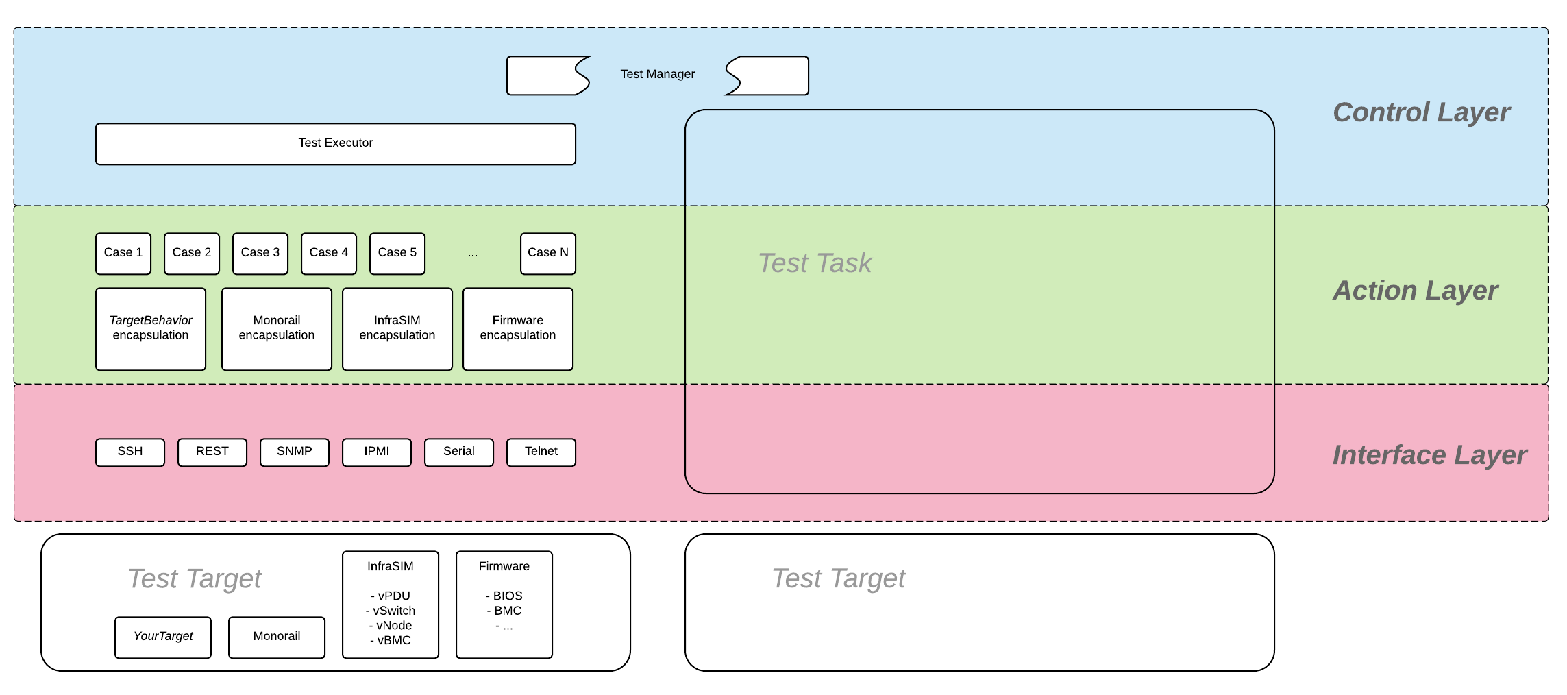
For any test target specified, those target behavior encapsulation need to be developed and a set of tests cases need to be added on top of encapsulation layer. Write test case described how to work out one test cases against infraSIM. Below sections introduced all details about setting up buffer and execute infraSIM testing with it.
7.3.1. Setup environment
Refer to the section 7.1 Physical Servers and ESXi Environment Setup.
Code:
git clone https://github.com/InfraSIM/test.git
Install necessary package:
sudo python test/install/PackageInstall.py
7.3.2. Define environment
You can see a configuration file example in test/configure/stack_example.json. To test your environment, you must define your environment in a file, and it must be in a valid JSON format.
Define the overall test environment.
- (Optional) vRackSystem - The test may leverage vRackSystem and have REST talk.
- available_Hypervisor - A list of hypervisors information. If your test has to handle hypervisors, this attribute is a required.
- vRacks - A list of virtual racks you have built.
{
    "vRackSystem": {},
    "available_HyperVisor": [],
    "vRacks": [],
}
(Optional) Define vRackSystem key information for REST interaction, this definition can be an empty dictionary:
{
    "protocol": "http",
    "ip": "192.168.1.1",
    "port": 8888,
    "username": "admin",
    "password": "admin",
    "root": "/api/v1"
}
Specify hypervisor information using available_HyperVisor.
For a single definition, here is an example:
{
    "name": "hyper1",
    "type": "ESXi",
    "ip": "192.168.1.2",
    "username": "username",
    "password": "password"
}
Specify a list of vRacks. Each definition includes:
- name - any name you like.
- hypervisor - The hypervisor you used in above definition. All virtual node, PDU, and switch are deployed on this hypervisor.
- vPDU - A list of virtual PDU definition. The list can be empty.
- vSwitch - A list of virtual switch definition. The list can be empty.
- vNode - A list of virtual node definition. The list can be empty.
They are organized in the following list:
{
    "name": "vRack1",
    "hypervisor": "hyper1",
    "vPDU": [],
    "vSwitch": [],
    "vNode": []
}
Specify a list of virtual PDUs. For each definition, you need to maintain:
- name - virtual PDU’s name in hypervisor
- datatstore - on which datastore this PDU is deployed.
- community - control community for SNMP access.
- ip - PDU IP
- outlet - A mapping of outlet to corresponding control password.
Example:
{
    "name": "vpdu_1",
    "datastore": "Datastore01",
    "community": "foo",
    "ip": "172.31.128.1",
    "outlet": {
        "1.1": "bar",
        "1.2": "bar",
        "1.3": "bar"
    }
}
vSwitch is currently not enabled.
Specify a list of virtual nodes. For each definition, you need to maintain:
- name - The virtual node’s name in hypervisor.
- datastore - The datastore this node is deployed on.
- power - A list of power control connection, each connection defines a specific PDU and outlet, you may have two power control, if this list is empty, node will not be controlled by any PDU.
- network - A definition for connection to virtual switch, currently not used.
- bmc - A definition on how to access virtual BMC of this node, including IP, username and password for ipmi over LAN access.
Example:
{
    "name": "vnode_a_20160126114700",
    "datastore": "Datastore01",
    "power": [
        {"vPDU": "vpdu_1", "outlet": "1.1"},
    ],
    "network": [],
    "bmc": {
        "ip": "172.31.128.2",
        "username": "admin",
        "password": "admin"
    }
}
Verify every IP is available from your test execution environment!
Verify PDU can access substream hypervisor! (see chapter 7.1.3 vPDU Configuration for detail)
7.3.3. Case Runtime Data
Case Runtime Data used to maintain some specific data for different test objects. These data generally require the user to add and update manually. For example, if you want to test one type of sensor for multiple nodes, you need to add and update sensor ID corresponds to each node.
Configuration file:
Case Runtime Data is defined in the json file which have same name with case script. If name of case script is T0000_test_HelloWorld.py, the name of runtime data shall be T0000_test_HelloWorld.json.
Here’s an example:
[
    {
        "name_1": "value_1",
        "name_2": "value_2"
    }
]
If your configuration json like above, you can get “value_1” by call self.data[“name_1”] in test case.
Here’s another example:
[
    {
        "node_1": "0x00",
        "node_2": "0x01"
    },
    {
        "node_1": "0x02",
        "node_2": "0x03"
    }
]
If your configuration json has two objects in an array like above, same case shall be run twice for each runtime data.
You will get “0x00” by call self.data[“node_1”] in test case for the first time, and “0x02” for the second time.
Test Result:
You shall get two separate result and a summary. Case’s final result is the worst result for all execution.
For example, if the case “failed” in first time and “passed” in second time, the final result is still “failed”, the summary will list all run results.
7.3.4. Run test
Trigger test:
cd test
python puffer.py -s infrasim --stack=<your_configuration>
<your_configuration> can be an absolute or related path of your configuration file. About how to run test, please check readme for detail:
cat README.md
You log file is kept in a folder of log/InfraSIM, each test task is packaged in a folder with time stamp as it’s folder name.
Notice: Please follow How to write test case to write a new test case.